What Best Describes a Simple Series Circuit
However in a parallel circuit components. Such connection is also termed as an end to end connection or a cascade connection.
The Simple Circuit
Draw the same.

. Help mount a lightning rod on top of the school. Here in the parallel circuit however the opposite is true. With each of these two basic circuit configurations we have specific sets of rules describing voltage current and resistance relationships.
And voltage drops add to equal a. Can be used as an adjustable voltage divider. If you put more lamps into a series circuit the lamps will be dimmer than before.
Cara wants to make her school a safer place to be during a lightning storm. Well explore parallel circuits in detail in another lesson. There is a single path for the flow of current.
Rules regarding Series and Parallel Circuits. Current flows along one pathwayB. It has 3 light bulbs.
Analyzing Series Circuits with Random Unknowns When trying to analyze a series circuit keep the following principles in mind. The current is the same in all parts of a series circuit. The flow of electricity comes from the switch.
Electric current flowing through the same and have the same direction throughout the entire circuit. They can either be connected in series or in parallel combinations. When you turn off a lamp youre really just breaking the series circuit.
Which best describes a simple series circuit. In summary a series circuit is defined as having only one path through which current can flow. From this definition three rules of series circuits follow.
A series circuit is one in which every component is arranged in a series connection. All components share the same. A series circuit is a circuit in which two components share a common node and the same current flows through them.
The same current flows through all three light bulbs. It has two light bulbs. Therefore a series circuit has the same current at all points in the circuit.
The flow of current comes from the light bulb. Electricity flows along one pathway. A series circuit is one in which numerous resistances are linked one after the other.
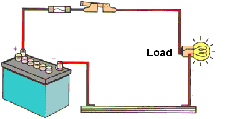
The same current flows through both light bulbs. Electricity flows along one pathway. When the switch is turned on current flows through the bulb first then the solenoid and last the motor.
Each charge passing through the loop of the external circuit will pass through each resistor in consecutive fashion. A circuit with a battery and two lamps connected in series. If I is known for one component use this value in all components.
This circuit is a series circuit because. The flow of electricity comes from the light bulb. All components share the same equal current.
Is so named because the voltage drop across any resistor in the series circuit is divided down from the total voltage by an amount proportional to that resistance value in relation to the total resistance. The flow of electricity comes from. Electricity flows along one pathway The flow of electricity comes from the switch Electricity flows along many pathways The flow of electricity comes from the light bulb.
Which of the following best describes a series circuit A. You can think of a series circuit as a set of parts that are connected end to end. The circuit right and left is another example of a series circuit.
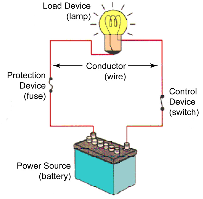
In a series circuit each device is connected in a manner such that there is only one pathway by which charge can traverse the external circuit. Which best describes a simple series circuit. A fuse opens an electric circuit when the current gets too high.
In the series circuit where the total resistance was the sum of the individual resistances the total was bound to be greater than any one of the resistors individually. This causes the bulb to light the solenoid to be activated and the motors spindle to rotate. A fuse is a type of insulator that adds resistance to an electric circuit.
Draw a simple series circuit and explain how it works. Electricity flows along many pathways. If I is unknown it may be calculated in one of two ways.
All components share the same current. Which best describes a series circuit. We say that the individual resistances diminish rather than add to make the total.
Electricity flows along one pathway. The picture shows an electrical circuit. Is a series arrangement of resistors connected to a voltage source.
20 Questions Show answers. A series circuit connects devices in series providing one single pathway for electron movement. A circuit with more than one path for energy to travel on is an.
Voltage drops add to equal total voltage. When there are two or more electrical devices in a circuit with an energy source there are a couple of basic ways by which we connect them. The voltage across various parts of the circuit.
In basic terms the series circuit is made up of a power source that travels through a path connected to the switch then up to the bulb and back again. A series circuit is an electric circuit that has only one pathway for electric current to take. Resistances add to equal a larger total resistance.
Which best describes a simple series circuit. This principle completes our triad of rules for parallel circuits just as series. The flow of electricity comes from.
A fuse strengthens electrical wires by binding them together. Current flows along many pathwaysC. Divide VT by RT.
The flow of current comes from the switchD. The total resistance of the circuit is equal to the sum of the individual resistances in the circuit together. Resistances add to equal total resistance.
Important features of the series circuit. Which best describes a simple series circuit.

I Think This Picture Represents Best The Esquematic Diagram Because You See How All That Electric Electrical Circuit Diagram Circuit Diagram Electrical Diagram
The Simple Circuit

Bildergebnis Fur Circuits Series And Parallel Circuits Series Parallel Sound Science
Electrical Circuits Quizizz


Comments
Post a Comment